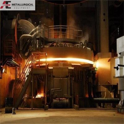
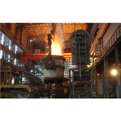
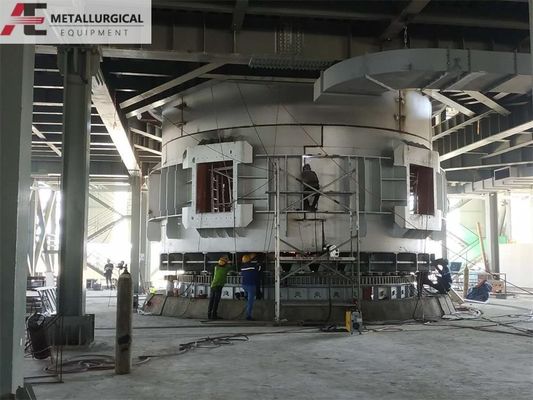
Ferro-legering Ondergedompelde Lichtboogoven: Een Oplossing voor Oververhitting en Roodkleuring van de Ovenbodem
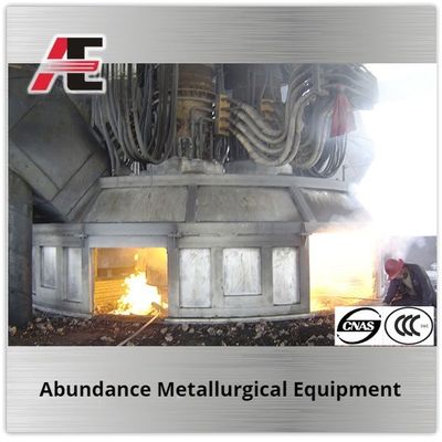
In traditionele ferro-legering ondergedompelde lichtboogovenswordt de ovenbekleding doorgaans geconstrueerd met voorgebakken koolstofblokken met brede, grove voegen. De ovenbelasting (of elektrodediepte) wordt geregeld door de primaire stroom aan te passen. Deze casestudy onderzoekt de primaire apparatuur van de twee 25,5 MVA ondergedompelde lichtboogovens van een bedrijf. Hoewel aanvankelijk een verfijnde fijnvoegmetseltechniek met semi-grafietkoolstofstenen werd gebruikt, traden er al drie maanden na de inbedrijfstelling oververhitting en roodkleuring van de ovenbodem op. Er werd een gedetailleerde post-mortem analyse uitgevoerd om de hoofdoorzaak te identificeren en een oplossing te ontwikkelen.
Operationele Tijdlijn en Incidentbeschrijving:
Oven nr. 1 werd in gebruik genomen en begon met de opwarmfase ("elektrische oven"). Het eerste vullen vond plaats op dag 6, met de eerste tap op dag 7.
Naarmate de oventemperatuur steeg, werd de secundaire spanning geleidelijk verhoogd en werd Oven nr. 2 op dag 12 opgestart.
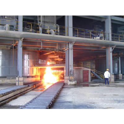
Op dag 43 van de werking van Oven nr. 1 werd een hard voorwerp aangetroffen dat de tapopening blokkeerde, een toestand die verbeterde nadat de tapopening was vervangen.
Op dag 83 ontstonden er operationele problemen, gekenmerkt door een overmatige slakvolume, een verminderde metaalopbrengst en frequente lage metaalproductie.
Op dag 90 overschreed de bodemtemperatuur van de oven 600°C en bereikte 1050°C op dag 95. Op dit punt vertoonde de stalen bodemschaal plaatselijke roodkleuring in vijf gebieden nabij de middellijn.
Oven nr. 2 vertoonde vervolgens een vergelijkbaar patroon, waarbij de bodemtemperatuur steeg van 425°C tot meer dan 550°C, waardoor een stillegging noodzakelijk was.
Oorzaakanalyse
Voortijdige roodkleuring of slijtage van de ovenbodem in ondergedompelde lichtboogovens is doorgaans het gevolg van een combinatie van factoren die verband houden met bekledingsmaterialen, constructiekwaliteit, dagelijkse werking en ovenontwerp. Voor dit incident werd de ovenbekleding geïdentificeerd als de belangrijkste factor.
1. Analyse van de Ovenbekleding (Primaire Factor)
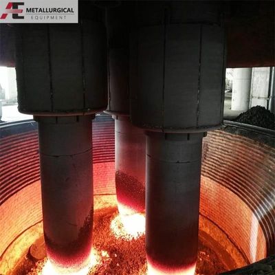
In een siliciummangaanlegeringsoven vormt de smeltzone een holte met hoge temperatuur ("kroes") rond de uiteinden van de drie elektroden, waar vaste lading wordt gesmolten en vergast. De temperaturen in deze holte bereiken 2000–3000°C. De hete zijde van de kroeswand is ongeveer 1800–2000°C, de koude zijde 1500–1800°C en de vaste lading grenzend aan de binnenwand van de ovenbekleding bereikt 1500–1700°C.
De mislukte fijnvoegmetselwerk gebruikte de volgende materialen (werkelijke geïnstalleerde diktes tussen haakjes):
N42 Vuurkleistenen (0,6345 m)
L75 Hoog-alumina stenen (0,335 m)
Voorgebakken (semi-grafiet) koolstofstenen (1,206 m)
Asbestvezelplaat isolatie (0,02 m)
Ovenschaal stalen plaat (0,03 m)
Voegmaterialen: Watervrije koolstofpasta, fosfaatslurry, hard hoog-alumina fijn poeder, lage temperatuur grove voeg elektrodepasta.
Semi-grafiet siliciumcarbide stenen werden ook gebruikt.
Een kritiek probleem werd geïdentificeerd in de thermische interface. Het verzachtingspunt van hoog-alumina stenen overschrijdt over het algemeen niet 1200°C. Als de werkomgeving dit overschrijdt, moet er een laag lichtgewicht koolstofstenen worden toegevoegd tussen de koolstofstenen en de hoog-alumina stenen om de interfacetemperatuur onder de 1200°C te verlagen. Deze buffer ontbrak.
Verder is de kwaliteit van het metselwerk cruciaal. Verschillende vuurvaste materialen hebben verschillende thermische uitzettingscoëfficiënten, waardoor een passend ontworpen en bemeten elastische bufferzone nodig is. Een zone die te dun is, kan de uitzetting niet opvangen, terwijl een zone die te dik is, onvoldoende weerstand biedt tegen de ovenschaal, waardoor de steenvoegen mogelijk breder worden.
Juiste voorverwarming ("bakken") van de bekleding volgens een gedefinieerde verwarmingscurve is essentieel, rekening houdend met de samenstelling van de bekleding (basis- versus warmteopslaglagen), vuurvaste eigenschappen, dikte, locatie en verwarmingsmethode. Andere operationele factoren, zoals controllerinstellingen, boogkenmerken en stroomverdeling, hebben ook een aanzienlijke invloed op de levensduur van de bekleding.
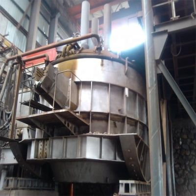
Post-Mortem van de Oven en Conclusies
Na een stillegging van een week werd Oven nr. 1 geleegd en geïnspecteerd:
1. Er werd een kokslayer van ongeveer 1,3 meter van de bovenkant van de oven aangetroffen, die 60% dikker was dan normaal.
2. Op ongeveer 2,4 meter diepte (in de driefasige elektrodenzone) was de koolstofsteenstructuur omhooggekomen. De normale ovendiepte was 3,6 meter.
De hoofdoorzaak van de roodkleuring van de bodem werd vastgesteld als thermisch geïnduceerde spanning in de steenbekleding tijdens het opwarmen. Deze spanning veroorzaakte uitstulpingen, scheuren aan de bovenkant en daaropvolgende infiltratie van gesmolten metaal. De driehoekige configuratie van de koolstofstenen concentreerde deze thermische spanning, wat leidde tot plaatselijke "uitstulpings"-falen.
Aanbevolen Oplossing:
Hoewel traditionele constructie met brede voegen een levensduur van de bekleding van meer dan een jaar kan garanderen, is een robuustere oplossing vereist voor langere campagnes. De aanbevolen aanpak is om het metselwerk met voorgebakken koolstofblokken met brede voegen te vervangen door een koud-gestampte monolithische bekleding. Als alternatief kan het gebruik van een fijnvoegmetseltechniek met zelfbakkende koolstofblokken op betrouwbare wijze een levensduur van de ovenbekleding van ten minste drie jaar garanderen. Het succes van deze methoden hangt kritisch af van het juiste ontwerp en de juiste selectie van ovenbekledingsmaterialen, met name het waarborgen van voldoende thermische buffering op materiaaloppervlakken en het opvangen van thermische uitzetting.
Wij zijn een professionele fabrikant van elektrische ovens. Voor verdere vragen, of als u ondergedompelde lichtboogovens, elektrische boogovens, pan-raffinageovens of andere smeltapparatuur nodig heeft, aarzel dan niet om contact met ons op te nemen via susan@aeaxa.com

 Uw bericht moet tussen de 20-3.000 tekens bevatten!